ASUS P5E3 Deluxe Overclocking: DDR3 Takes Front Stage
by Kris Boughton on November 20, 2007 4:00 AM EST- Posted in
- CPUs
Board Layout and Features
ASUS decided to surround the LGA775 socket on all four sides with a generous portion of copper heatpipe-pierced heatsinks, in effect thermally adjoining the memory control hub (MCH) and both sets of power MOSFET banks. The portion of the cooler located between the CPU socket and memory DIMMs is "floating" above the board with a thin layer of electrically insulating material isolating it from the components below. As is usually the case, the stock mounting solution does not provide enough clamping pressure, resulting in increased thermal resistance that usually leads to higher component temperatures than would normally be experienced. We noticed this same problem on the abit IP35-Pro, although the ASUS design did provide better overall cooling.
The P5E3 Deluxe makes excellent use of an 8-phase power delivery system, a must for any board engineered to provide the high current required when pushing a quad-core processors well beyond stock speeds. Although the MOSFETs are completely capable of operating without issue over an exceptionally large temperature range (often able to survive temperatures reaching 120C or greater) it is the Northbridge (MCH) that we really worry about. Our testing has shown the X38 chipset to be particularly sensitive to sustained load temperatures in excess of about 50-55C.
The solution to correcting the lackluster mounting pressure was almost effortless (making us wonder why ASUS didn't make the extra effort and save us the trouble). We simply removed any hardware holding the heatpipe assembly to the board, cleaned all thermal surfaces with rubbing alcohol (making sure we allowed ample time for the board to completely dry), and then remounted the unit with a fresh coating of our favorite thermal paste. This time we used small machine screws and threaded nuts in place of the plastic pushpins. This allowed us to control the loading pressure, ensuring a secure bond between the copper and the heat sources. Looking at the picture above, please note the black replacement screws used to hold everything together. In the end, the effort we invested in improving our board's cooling efficiency resulted in more than an 8C drop in measured MCH load temperatures.
As we can see, ASUS has done a wonderful job of physically locating the DIMMs as close as possible to the MCH in an effort to minimize trace lengths and maximize overclocking potential. When combined with new design features on DDR3 modules, like fully terminated data and address signal lines and 2-phase power from the motherboard, these small changes can result in rather massive increases in memory operating frequencies with low voltages.
The X38 MCH provides official support for up to 8GB of low-voltage DDR3, meaning even the most memory intensive application running atop Windows Vista 64-bit should be happy. The primary 24-pin power connector is located on the bottom edge of the board with the supplementary 8-pin EPS12V power connector being located at the top of the board near the backplane.
Intel's ICH9R, although rated at no more than about 6W when operating, is connected to the stock board cooling solution using a single heatpipe - no doubt, we discovered the Southbridge heatsink is hotter for this very reason than it otherwise would be. The board provides six SATA ports, more than enough for most overclockers. Unfortunately, ASUS decided not to include an LED POST code reader somewhere making it difficult to determine exactly what the board is doing during the POST period.
The small blue header to the bottom of the board is used for clearing the BIOS should the need arise. We were pleasantly surprised as to how gracefully the board recovered from a failed setting - one quick full-power cycle and the board defaulted to safe settings allowing us to easily enter the BIOS and correct our mistake.
One of the features separating the X38 chipset from the mainstream segment P35 MCH is the addition of PCI-E 2.0 specification compatibility. The blue slots connect direct to the MCH and each provides the full 16 lanes of bandwidth - though truthfully, we can't see the additional bandwidth really helping much as PCI-E throughput often isn't the limiting factor, especially with PCI-E 2.0 already doubling the bandwidth for 1.x. The third x16 slot (black) can operate at either x1 or x4 speeds. Two PCI slots and one additional PCI-E x1 slot round out the board's expansion capabilities.
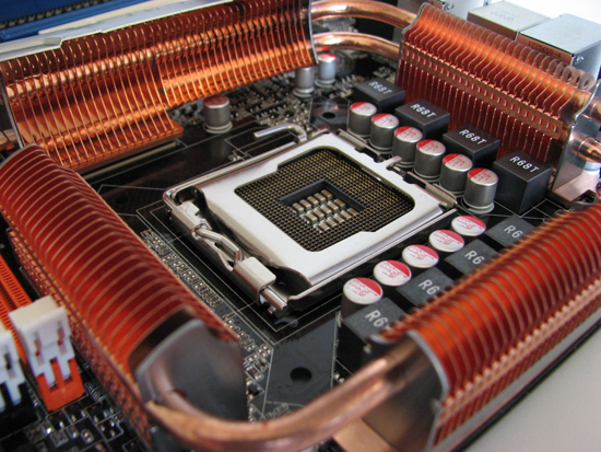 |
ASUS decided to surround the LGA775 socket on all four sides with a generous portion of copper heatpipe-pierced heatsinks, in effect thermally adjoining the memory control hub (MCH) and both sets of power MOSFET banks. The portion of the cooler located between the CPU socket and memory DIMMs is "floating" above the board with a thin layer of electrically insulating material isolating it from the components below. As is usually the case, the stock mounting solution does not provide enough clamping pressure, resulting in increased thermal resistance that usually leads to higher component temperatures than would normally be experienced. We noticed this same problem on the abit IP35-Pro, although the ASUS design did provide better overall cooling.
The P5E3 Deluxe makes excellent use of an 8-phase power delivery system, a must for any board engineered to provide the high current required when pushing a quad-core processors well beyond stock speeds. Although the MOSFETs are completely capable of operating without issue over an exceptionally large temperature range (often able to survive temperatures reaching 120C or greater) it is the Northbridge (MCH) that we really worry about. Our testing has shown the X38 chipset to be particularly sensitive to sustained load temperatures in excess of about 50-55C.
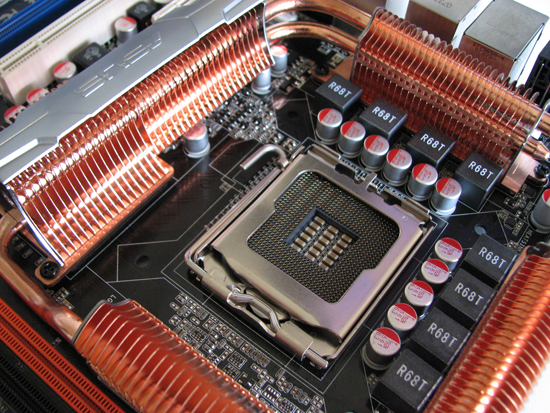 |
The solution to correcting the lackluster mounting pressure was almost effortless (making us wonder why ASUS didn't make the extra effort and save us the trouble). We simply removed any hardware holding the heatpipe assembly to the board, cleaned all thermal surfaces with rubbing alcohol (making sure we allowed ample time for the board to completely dry), and then remounted the unit with a fresh coating of our favorite thermal paste. This time we used small machine screws and threaded nuts in place of the plastic pushpins. This allowed us to control the loading pressure, ensuring a secure bond between the copper and the heat sources. Looking at the picture above, please note the black replacement screws used to hold everything together. In the end, the effort we invested in improving our board's cooling efficiency resulted in more than an 8C drop in measured MCH load temperatures.
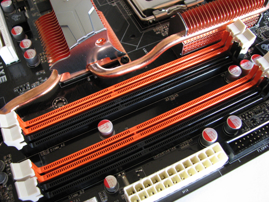 |
As we can see, ASUS has done a wonderful job of physically locating the DIMMs as close as possible to the MCH in an effort to minimize trace lengths and maximize overclocking potential. When combined with new design features on DDR3 modules, like fully terminated data and address signal lines and 2-phase power from the motherboard, these small changes can result in rather massive increases in memory operating frequencies with low voltages.
The X38 MCH provides official support for up to 8GB of low-voltage DDR3, meaning even the most memory intensive application running atop Windows Vista 64-bit should be happy. The primary 24-pin power connector is located on the bottom edge of the board with the supplementary 8-pin EPS12V power connector being located at the top of the board near the backplane.
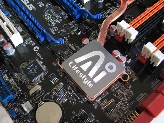 |
Intel's ICH9R, although rated at no more than about 6W when operating, is connected to the stock board cooling solution using a single heatpipe - no doubt, we discovered the Southbridge heatsink is hotter for this very reason than it otherwise would be. The board provides six SATA ports, more than enough for most overclockers. Unfortunately, ASUS decided not to include an LED POST code reader somewhere making it difficult to determine exactly what the board is doing during the POST period.
The small blue header to the bottom of the board is used for clearing the BIOS should the need arise. We were pleasantly surprised as to how gracefully the board recovered from a failed setting - one quick full-power cycle and the board defaulted to safe settings allowing us to easily enter the BIOS and correct our mistake.
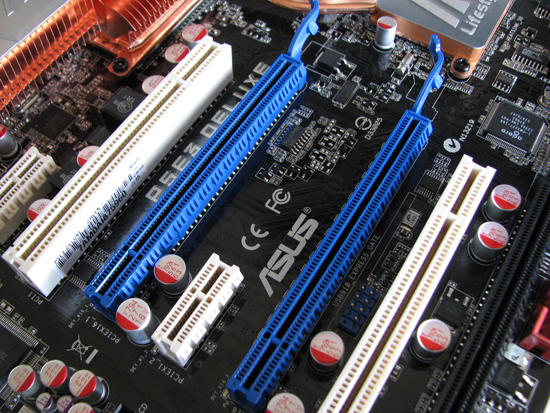 |
One of the features separating the X38 chipset from the mainstream segment P35 MCH is the addition of PCI-E 2.0 specification compatibility. The blue slots connect direct to the MCH and each provides the full 16 lanes of bandwidth - though truthfully, we can't see the additional bandwidth really helping much as PCI-E throughput often isn't the limiting factor, especially with PCI-E 2.0 already doubling the bandwidth for 1.x. The third x16 slot (black) can operate at either x1 or x4 speeds. Two PCI slots and one additional PCI-E x1 slot round out the board's expansion capabilities.


25 Comments
View All Comments
frede86 - Tuesday, September 2, 2008 - link
hey folksnice guide u made there m8.
but ive tryed to use that setup u recomment.
but doenst work. how come? is it because i use a dou core E8500?
Cheers
frede86 - Tuesday, September 2, 2008 - link
Core 2 dou*cEvin Ki - Saturday, February 23, 2008 - link
after reading the information on the AI transaction booster, and the Memset program, i decided to brave up, and give it a go. Memset indicated that my performance level was a 7. as my ddr2 CAS was 4, i assumed that the bios was relaxing my system a little. i simply disabled the booster option in bios with a relax of zero. rebooted, and re-ran Memset. nothing had changed. still a 7. any settings other than disabled and zero, in bios, will not POST. Memset allowed me to change the performance level to 6, apply, and save the change. nothing has changed in bios as a result of that change.my question is, what am i doing wrong, as i would expect to have seen something different in Memset with changing the bios to disabled and in effect lessening the relax?
i apologize if i have somehow missed the whole point, and do not understand this memory tweaking concept.
thanks
jwigi - Thursday, February 14, 2008 - link
Hi I have a P5k Premium and the contact between the heatsinks and the board aren't very good, i was wondering what size of screw you used and also if you needed to put any springs on them, i'm thinking of doing the same 'mod' you've done in your article on my board...thanks
plextor10000 - Thursday, January 10, 2008 - link
I was already one day playing with the settings of the mainboard, first tried to boost the E6850 from default 3Ghz to 3.6 , but could not make it stable in benchmarksSwitched to the Q6600 - and followed the guide , decrease the voltage for the CPU to 1.375 , for safety .
After step by step, i increased from 2.4 without any issue to 3.6 , running stable with my patriot 1333 on 1600
Thank you for this guide. Can i use the same settings for the E6850 also , or do i modyfie some settings to blaze the clocks of it ??
Ryujin - Sunday, January 6, 2008 - link
I recently got this board, and after reading this article, I really want to follow the advice therein and remove the thermal pads underneath the heatpipes/heatsinks and replace them with thermal paste, and replace all the plastic push-pins with screws/nuts.I've yet to start fiddling with the board, as I am still waiting for the CPU to arrive. A few pieces of advice I was looking for to ease my mind though:
- Would I be mad using Arctic Silver thermal compound, considering conductivity issues? (I could get ceramique, which is non-conductive, but it'll take quite a while, through the channels I wish to use).
- What diameter / length screws do you recommend? I figure 10mm M3 screws with lock nuts should do the trick... If they're too long, I should be able to screw them in with the heads facing the MB-tray.
- I'm going with a liquid cooling solution for my CPU. The P5E3 Deluxe included two fans that can be placed atop the heatsinks surrounding the CPU-socket for just such an occasion. However, I suspect they're rather noisy (are they?). Also, the case I'm using is the Coolermaster Cosmos, which does have ample chassi fans, so I'm wondering it is really necessary (time will tell, but I was wondering if anyone has any opinions on the subject).
cheers
kmmatney - Tuesday, November 20, 2007 - link
OK, looking at the graphs, it just seems like all I'm seeing is the benchmarks getting better with higher overall cpu speed. The overclocking guide was good, but the benchmarks are hard to figure out, since memory speed and cpu speed are getting higher at the same time.kmmatney - Tuesday, November 20, 2007 - link
OK, figured it out - we just need to compare the Asus P5E3 scores versus the Asus Maximums scores at (8 X 465) to see how much DDR3 improves things over DDR2. Seems to be 1%-5%. Yawn...TA152H - Tuesday, November 20, 2007 - link
When I read the article for the x48, I mentioned that it made no sense for the three chipsets unless the x48 was DDR3 only. Well, I have found out from another site that it will be DDR3 only.That makes the x38 really only useful as a DDR2 chipset, after the x48 is available. This assumes Intel did the right thing of course, and all the ugly overhead for DDR2 is removed from the x48. But if it is, you'd have to be a fool to buy the x38 with DDR3, since it is second best, and has overhead from a function that will not be present on the motherboard. It will give you more heat, and more power use for something that is completely useless. I didn't like Intel including both, but I guess it was to transition to DDR3, so it was a necessary evil until the x48 comes out.
retrospooty - Friday, November 23, 2007 - link
actually, that isnt true. X48 is just an X38 selected out of speed bin to be the fastest. They were going to market it as only DDR3 (that was a marketing decision not a functionality decision) but have since changed their minds.http://www.fudzilla.com/index.php?option=com_conte...">http://www.fudzilla.com/index.php?optio...amp;task...
Either way your arguments are pretty one sided. Even with DDR3 highly overclocked to 2ghz its really only a slight bit faster then DDR2. In fact DDR2 at 1000mhz 4-4-4 beats DDR3 at 2000mhz @ 9-9-9 in most real world tests and apps. Intel is currently going with tri-channel DDR3 on the next gen CPU (nehalem) with internal memory controller. Then and ONLY then is DDR3 going to be worthwhile, and even then its only worthwhile because Nehalem chipsets wont support DDR2. DDR3 is a minor speed bump not worthy of spending money on until Nehalem comes out.